The documentation set for this product strives to use bias-free language. For the purposes of this documentation set, bias-free is defined as language that does not imply discrimination based on age, disability, gender, racial identity, ethnic identity, sexual orientation, socioeconomic status, and intersectionality. Exceptions may be present in the documentation due to language that is hardcoded in the user interfaces of the product software, language used based on RFP documentation, or language that is used by a referenced third-party product. Learn more about how Cisco is using Inclusive Language.
This document describes the best practices to use for virtual Port Channels (vPC) on Cisco Nexus 9000 (9k) Series Switches.
Hot Standby Router Protocol (HSRP), Virtual Router Redundancy Protocol (VRRP), Link Aggregation Control Protocol (LACP) are also included in this base license.
Layer 3 features like Open Shortest Path First (OSPF) protocol or Intermediate-System-to-Intermediate System (ISIS) protocol require LAN_ENTERPRISE_SERVICES_PKG license.
The information in this document is based on these software and hardware versions:
The information in this document was created from the devices in a specific lab environment. All of the devices used in this document started with a cleared (default) configuration. If your network is live, ensure that you understand the potential impact of any command.
vPC Fabric Peering provides an enhanced dual-homing access solution without the overhead of waste physical ports for vPC Peer Link.
This document applies to:
This document also covers In-Service Software Upgrade (ISSU) operations related to vPC and gives details about the latest vPC enhancements (delay restore, Network Virtual Interface (NVE) interface timers).
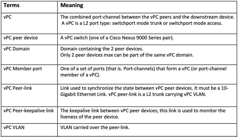
vPC is a virtualization technology that presents both Cisco Nexus 9000 Series paired devices as a unique Layer 2 logical node to access layer devices or endpoints.
vPC belongs to Multichassis EtherChannel (MCEC) family of technology. A virtual port channel (vPC) allows links that are physically connected to two different Cisco Nexus 9000 Series devices to appear as a single port channel to a third device.
The third device can be a switch, server, or any other networking device that supports link aggregation technology.
vPC provides these technical benefits:
vPC offers these immediate operational and architectural advantages for users:
vPC leverages both hardware and software redundancy aspects through these methods:
From STP, vPC eliminates STP blocked ports and uses all available uplink bandwidth. STP is used as a fail safe mechanism and does not dictate L2 path for vPC-attached devices.
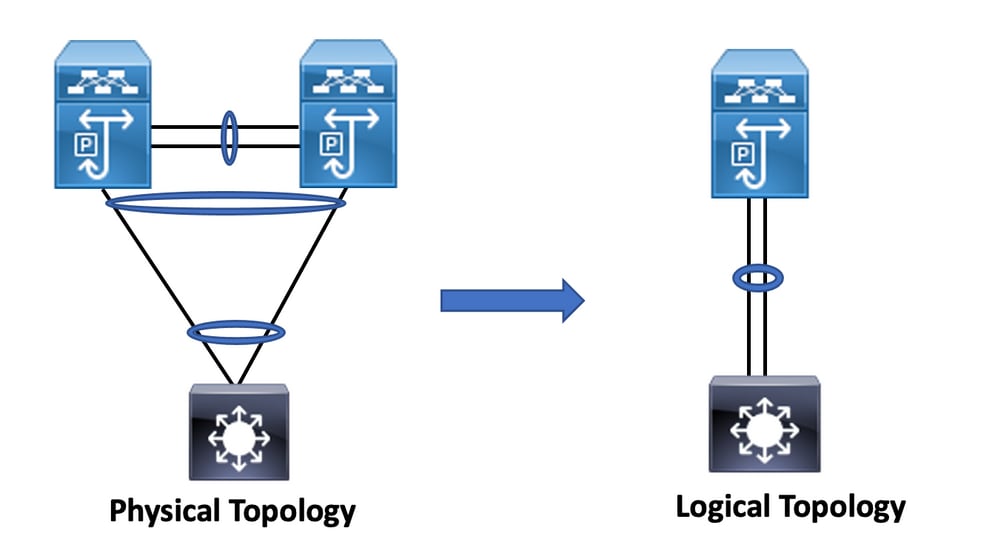
Within a vPC domain, a user can connect access devices in multiple ways: vPC-attached connections that leverage active/active behavior with port-channel, active/standby connectivity include STP, and single attachment without STP that runs on the access device.
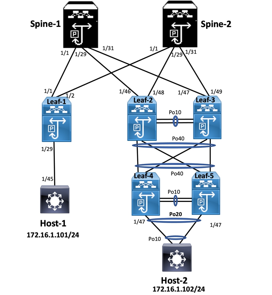
In the diagram, host connects to a pair of Nexus 9000 switches includes vPC domain id, but host-configured switches do not run vPC themselves. The access switch/host registers uplink as a simple port-channel without vPC knowledge.
Leaf-1
vlan 2
vn-segment 10002
vlan 10
vn-segment 10010
route-map PERMIT-ALL permit 10
vrf context test
vni 10002
rd auto
address-family ipv4 unicast
route-target both auto
route-target both auto evpn

interface nve1
no shutdown
host-reachability protocol bgp
source-interface loopback1
member vni 10002 associate-vrf
member vni 10010
suppress-arp
mcast-group 239.1.1.1

interface loopback0
ip address 10.1.1.1/32
ip router ospf 100 area 0.0.0.0
ip pim sparse-mode
no shutdown

interface loopback1
ip address 10.2.1.1/32
ip router ospf 100 area 0.0.0.0
ip pim sparse-mode
no shutdown

Leaf-2
vlan 2
 vn-segment 10002
 vlan 10
 vn-segment 10010
 route-map PERMIT-ALL permit 10
vrf context test
 vni 10002
 rd auto
 address-family ipv4 unicast
 route-target both auto
 route-target both auto evpn

interface nve1
 no shutdown
host-reachability protocol bgp
advertise virtual-rmac
source-interface loopback1
member vni 10002
associate-vrf member
vni 10010
suppress-arp
mcast-group 239.1.1.1

interface loopback1
ip address 10.2.1.4/32
ip address 10.2.1.10/32 secondary
ip router ospf 100 area 0.0.0.0
ip pim sparse-mode
icam monitor scale

interface loopback0
ip address 10.1.1.4/32
ip router ospf 100 area 0.0.0.0
ip pim sparse-mode
no shutdown

Leaf-2(config-if)# show run vpc
feature vpc

vpc domain 1
peer-switch
peer-keepalive destination 10.201.182.26 source 10.201.182.25
peer-gateway
ip arp synchronize

interface port-channel10
 vpc peer-link

interface port-channel20
vpc 20

Leaf-3
vlan 2
 vn-segment 10002
 vlan 10
 vn-segment 10010
 route-map PERMIT-ALL permit 10
vrf context test
 vni 10002
 rd auto
 address-family ipv4 unicast
 route-target both auto
 route-target both auto evpn

interface nve1
 no shutdown
host-reachability protocol bgp
advertise virtual-rmac
source-interface loopback1
member vni 10002
associate-vrf member
vni 10010
suppress-arp
mcast-group 239.1.1.1

 interface loopback1
ip address 10.2.1.3/32
ip address 10.2.1.10/32 secondary
ip router ospf 100 area 0.0.0.0
ip pim sparse-mode
icam monitor scale

interface loopback0
ip address 10.1.1.3/32
ip router ospf 100 area 0.0.0.0
ip pim sparse-mode

Leaf-3(config-if)# show run vpc
feature vpc

vpc domain 1
peer-switch
peer-keepalive destination 10.201.182.25 source 10.201.182.26
peer-gateway
ip arp synchronize

interface port-channel10
vpc peer-link

interface port-channel20
vpc 20

Spine-1
interface loopback0
 ip address 10.3.1.1/32
 ip router ospf 100 area 0.0.0.0
 ip pim sparse-mode

Host-1
interface Vlan10
no shutdown
vrf member test
ip address 172.16.1.101/25


Host-2
interface Vlan10
no shutdown
vrf member test
ip address 172.16.1.102/25
Use this section to confirm that your configuration works properly.
ip interface Status for VRF "test"(3)
Interface ip Address Interface Status
Vlan10 172.16.1.102 protocol-up/link-up/admin-up
HOST-B(config)# ping 172.16.1.101 vrf test
PING 172.16.1.101 (172.16.1.101): 56 data bytes
64 bytes from 172.16.1.101: icmp_seq=0 ttl=254 time=1.326 ms
64 bytes from 172.16.1.101: icmp_seq=1 ttl=254 time=0.54 ms
64 bytes from 172.16.1.101: icmp_seq=2 ttl=254 time=0.502 ms
64 bytes from 172.16.1.101: icmp_seq=3 ttl=254 time=0.533 ms
64 bytes from 172.16.1.101: icmp_seq=4 ttl=254 time=0.47 ms
--- 172.16.1.101 ping statistics ---
5 packets transmitted, 5 packets received, 0.00% packet loss round-trip min/avg/max = 0.47/0.674/1.326 ms HOST-B(config)#
IP Interface Status for VRF "test"(3)
interface IP Address Interface Status
Vlan10 172.16.1.101 protocol-up/link-up/admin-up
Host-A(config-if)#
Host-A(config-if)# ping 172.16.1.102 vrf test
PING 172.16.1.102 (172.16.1.102): 56 data bytes
64 bytes from 172.16.1.102: icmp_seq=0 ttl=254 time=1.069 ms
64 bytes from 172.16.1.102: icmp_seq=1 ttl=254 time=0.648 ms
64 bytes from 172.16.1.102: icmp_seq=2 ttl=254 time=0.588 ms
64 bytes from 172.16.1.102: icmp_seq=3 ttl=254 time=0.521 ms
64 bytes from 172.16.1.102: icmp_seq=4 ttl=254 time=0.495 ms
--- 172.16.1.102 ping statistics ---
5 packets transmitted, 5 packets received, 0.00% packet loss round-trip min/avg/max = 0.495/0.664/1.069 ms Host-A(config-if)#
This section provides information you can use to troubleshoot your configuration.
Leaf-2(config-if)# show vpc bri
Legend:
(*) - local vPC is down, forwarding via vPC peer-link
vPC domain id : 1
Peer status : peer adjacency formed ok
vPC keep-alive status : peer is alive
Configuration consistency status : success
Per-vlan consistency status : success
Type-2 consistency status : success
vPC role : primary
Number of vPCs configured : 1
Peer Gateway : Enabled
Dual-active excluded VLANs : -
Graceful Consistency Check : Enabled
Auto-recovery status : Disabled
Delay-restore status : Timer is off.(timeout = 30s)
Delay-restore SVI status : Timer is off.(timeout = 10s)
Delay-restore Orphan-port status : Timer is off.(timeout = 0s)
Operational Layer3 Peer-router : Disabled
Virtual-peerlink mode : Disabled
vPC Peer-link status
——————————————————————————————————
id Port Status Active vlans
-- ---- ------ -------------------------------------------------
1 Po10 up 1-2,10
Please check "show vpc consistency-parameters vpc " for the consistency reason of down vpc and for type-2 consistency reasons for
any vpc.
Leaf-3(config-if)# show vpc bri
Legend:
(*) - local vPC is down, forwarding via vPC peer-link
vPC domain id : 1
Peer status : peer adjacency formed ok
vPC keep-alive status : peer is alive
Configuration consistency status : success
Per-vlan consistency status : success
Type-2 consistency status : success
vPC role : secondary
Number of vPCs configured : 1
Peer Gateway : Enabled
Dual-active excluded VLANs : -
Graceful Consistency Check : Enabled
Auto-recovery status : Disabled
Delay-restore status : Timer is off.(timeout = 30s)
Delay-restore SVI status : Timer is off.(timeout = 10s)
Delay-restore Orphan-port status : Timer is off.(timeout = 0s)
Operational Layer3 Peer-router : Disabled
Please check "show vpc consistency-parameters vpc " for the consistency reason of down vpc and for type-2 consistency reasons for
any vpc.
Leaf-2
Leaf-2(config-vpc-domain)# show run vpc
feature vpc

vpc domain 1
peer-switch
peer-keepalive destination 10.201.182.26
virtual peer-link destination 10.1.1.3 source 10.1.1.4 dscp 56
peer-gateway
ip arp synchronize

interface port-channel10
vpc peer-link

interface Ethernet1/46
mtu 9216
port-type fabric
ip address 192.168.2.1/24
ip ospf network point-to-point
ip router ospf 100 area 0.0.0.0
ip pim sparse-mode
no shutdown

Leaf-3
Leaf-3(config-vpc-domain)# show run vpc
feature vpc

vpc domain 1
peer-switch
peer-keepalive destination 10.201.182.25
virtual peer-link destination 10.1.1.4 source 10.1.1.3 dscp 56

peer-gateway
ip arp synchronize

interface port-channel10
vpc peer-link

interface Ethernet1/47
mtu 9216
port-type fabric
ip address 192.168.1.1/24
ip ospf network point-to-point
ip router ospf 100 area 0.0.0.0
ip pim sparse-mode
no shutdown
Use this section in order to confirm that your configuration works properly.
show vpc brief
show vpc role
show vpc virtual-peerlink vlan consistency
show vpc fabric-ports
show vpc consistency-para global
show nve interface nve 1 detail
Leaf-2
Leaf-2(config-if-range)# show run vpc
feature vpc

vpc domain 1
peer-switch
peer-keepalive destination 10.201.182.26 source 10.201.182.25
peer-gateway
ip arp synchronize

interface port-channel10
 vpc peer-link

interface port-channel20
 vpc 20

interface port-channel40
 vpc 40

Leaf-3
Leaf-3(config-if-range)# show run vpc
feature vpc

vpc domain 1
peer-switch
peer-keepalive destination 10.201.182.25 source 10.201.182.26
peer-gateway
ip arp synchronize

interface port-channel10
 vpc peer-link

interface port-channel20
 vpc 20

interface port-channel40
 vpc 40

Leaf-4
Leaf-4(config-if)# show run vpc
feature vpc

vpc domain 2
 peer-switch
 peer-keepalive destination 10.201.182.29 source 10.201.182.28
 peer-gateway

interface port-channel10
 vpc peer-link

interface port-channel20
 vpc 20

interface port-channel40
 vpc 40

Leaf-5
Leaf-5(config-if)# show running-config vpc
feature vpc

vpc domain 2
 peer-switch
 peer-keepalive destination 10.201.182.28 source 10.201.182.29
 peer-gateway

interface port-channel10
 vpc peer-link

interface port-channel20
 vpc 20

interface port-channel40
 vpc 40
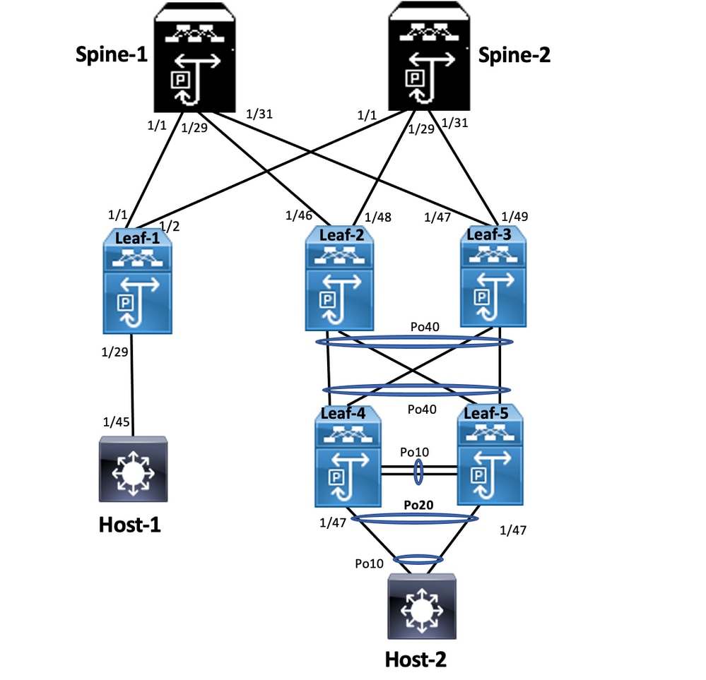
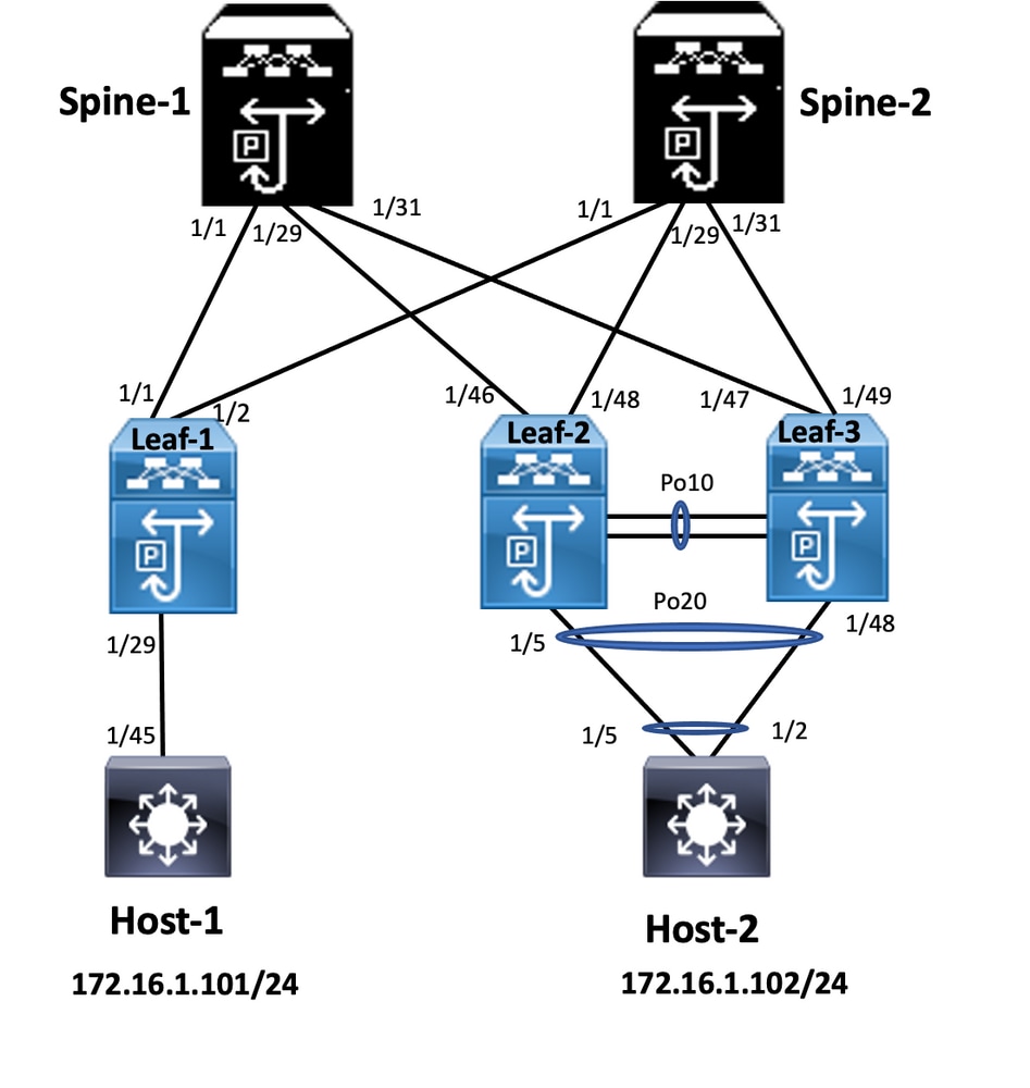
In double-sided vPC, both the Nexus 9000 switches run vPC. Each vPC pair of Nexus 9000 switches is connected to the aggregation vPC pair with a unique vPC.
Leaf-2
Leaf-2(config-if-range)# show run vpc
feature vpc
vpc domain 1
peer-switch
peer-keepalive destination 10.201.182.26
virtual peer-link destination 10.1.1.3 source 10.1.1.4 dscp 56
peer-gateway
ip arp synchronize
interface port-channel10
vpc peer-link
interface port-channel20
vpc 20
interface port-channel40
vpc 40
Leaf-3
Leaf-3(config-if-range)# show run vpc
feature vpc
vpc domain 1
peer-switch
peer-keepalive destination 10.201.182.25
virtual peer-link destination 10.1.1.4 source 10.1.1.3 dscp 56
peer-gateway
ip arp synchronize
interface port-channel10
vpc peer-link
interface port-channel20
vpc 20
interface port-channel40
vpc 40
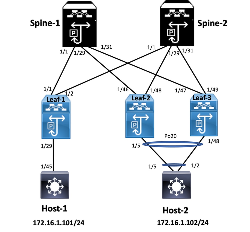
Leaf-4 and Leaf-5 configuration is similar as double-sided vPC.
This section provides information you can use in order to troubleshoot your configuration.
Leaf-4(config-if)# show spanning-tree
Spanning tree enabled protocol rstp
Root ID Priority 32778
Port 4105 (port-channel10)
Hello Time 2 sec Max Age 20 sec Forward Delay 15 sec
Bridge ID Priority 32778 (priority 32768 sys-id-ext 10)
Hello Time 2 sec Max Age 20 sec Forward Delay 15 sec
Interface Role Sts Cost Prio.Nbr Type
Po10 Root FWD 4 128.4105 (vPC peer-link) Network P2p
Po20 Desg FWD 1 128.4115 (vPC) P2p
Po40 Root FWD 1 128.4135 (vPC) P2p
Spanning tree enabled protocol rstp
Root ID Priority 32788
This bridge is the root
Hello Time 2 sec Max Age 20 sec Forward Delay 15 sec
Bridge ID Priority 32788 (priority 32768 sys-id-ext 20)
Hello Time 2 sec Max Age 20 sec Forward Delay 15 sec
Interface Role Sts Cost Prio.Nbr Type
Po10 Root FWD 4 128.4105 (vPC peer-link) Network P2p
Po20 Desg FWD 1 128.4115 (vPC) P2p
Po40 Desg FWD 1 128.4135 (vPC) P2p
Leaf-5(config-if)# show spanning-tree
Spanning tree enabled protocol rstp
Root ID Priority 32778
Port 4135 (port-channel40)
Hello Time 2 sec Max Age 20 sec Forward Delay 15 sec
Bridge ID Priority 32778 (priority 32768 sys-id-ext 10)
Hello Time 2 sec Max Age 20 sec Forward Delay 15 sec
Interface Role Sts Cost Prio.Nbr Type
Po10 Desg FWD 4 128.4105 (vPC peer-link) Network P2p
Po20 Desg FWD 1 128.4115 (vPC) P2p
Po40 Root FWD 1 128.4135 (vPC) P2p
Spanning tree enabled protocol rstp
Root ID Priority 32788
This bridge is the root
Hello Time 2 sec Max Age 20 sec Forward Delay 15 sec
Bridge ID Priority 32788 (priority 32768 sys-id-ext 20)
Hello Time 2 sec Max Age 20 sec Forward Delay 15 sec
Interface Role Sts Cost Prio.Nbr Type
Po10 Desg FWD 4 128.4105 (vPC peer-link) Network P2p
Po20 Desg FWD 1 128.4115 (vPC) P2p
Po40 Desg FWD 1 128.4135 (vPC) P2p
Leaf-2(config-if-range)# show spanning-tree
Spanning tree enabled protocol rstp
Root ID Priority 32769
Hello Time 2 sec Max Age 20 sec Forward Delay 15 sec
Bridge ID Priority 32769 (priority 32768 sys-id-ext 1)
Hello Time 2 sec Max Age 20 sec Forward Delay 15 sec
Interface Role Sts Cost Prio.Nbr Type
Eth1/47 Desg FWD 4 128.185 P2p
Spanning tree enabled protocol rstp
Root ID Priority 32778
This bridge is the root
Hello Time 2 sec Max Age 20 sec Forward Delay 15 sec
Bridge ID Priority 32778 (priority 32768 sys-id-ext 10)
Hello Time 2 sec Max Age 20 sec Forward Delay 15 sec
Interface Role Sts Cost Prio.Nbr Type
Po10 Desg FWD 4 128.4105 (vPC peer-link) Network P2p
Po40 Desg FWD 1 128.4135 (vPC) P2p
Eth1/47 Desg FWD 4 128.185 P2p
Leaf-3(config-if-range)# show spanning-tree
Spanning tree enabled protocol rstp
Root ID Priority 32778
This bridge is the root
Hello Time 2 sec Max Age 20 sec Forward Delay 15 sec
Bridge ID Priority 32778 (priority 32768 sys-id-ext 10)
Hello Time 2 sec Max Age 20 sec Forward Delay 15 sec
Interface Role Sts Cost Prio.Nbr Type
Po10 Root FWD 4 128.4105 (vPC peer-link) Network P2p
Po40 Desg FWD 1 128.4135 (vPC) P2p
This section describes the best practices for the non-disruptive software upgrade, use Cisco ISSU when a vPC domain is configured. vPC System NX-OS Upgrade (or Downgrade) vPC feature is fully compatible with Cisco ISSU.
In a vPC environment, ISSU is the recommended method to upgrade the system. The vPC system can be independently upgraded with no disruption to traffic. The upgrade is serialized and must be run one at a time. The configuration lock during ISSU prevents synchronous upgrades on both vPC peer devices to happen (configuration is automatically locked on other vPC peer device when ISSU is initiated). To perform ISSU operation, 1 single knob is needed.
Note: vPC with FEX (host vPC) also fully supports ISSU. There is zero packet loss when the upgraded vPC domain has FEX. Server dual-attached to 2 different FEX through a standard port-channel is not aware that the upgrade operation occurs in the network.
switch#install all nxos bootflash:
vPC peer device 1, 9K1 (loads the code first on primary or secondary vPC peer device has no importance) use ISSU. Note that other vPC peer device (9K2) has its configuration locked to protect against any operation on the switch.
Note: Upgrade 9k1 from 7.x to 9.3.8/9.3.9 caused 40g port down on vPC. If peer-link is connected with 40 G, it is recommended to upgrade both switches into 9.3.8/9.3.9 to bring 40G up or path needs to follow: I7(7) – 9.3(1) – 9.3(9).
show version
show module
show spanning-tree summary
show vlan summary
show ip interface brief
show port-channel summary
show vpc
show vpc brief
show vpc role
show vpc peer-keepalives
show vpc statistics peer-keepalive
show vpc consistency-parameters global
show vpc consistency-parameters interface port-channel<>
show vpc consistency-parameters vlans
show run vpc all
show hsrp brief
show hsrp
show run hsrp
show hsrp interface vlan
Show vrrp
Show vrrp brief
Show vrrp interface vlan
Show run vrrp
show vpc
 show vpc statistics
 show ip route vrf all summary
 show ip mroute vrf all summary
 show ip interface brief
 show interface status
 show port-channel summary
 show hsrp brief
 Show vrrp brief
 show version
 show module
 show diagnostic results module all detail
 show license
 show license usage
 show system internal mts buffer summary|detail
 show logging logfile
 show logging nvram
Leaf-2(config)# vpc domain 1
Leaf-2(config-vpc-domain)# no auto-recovery
Leaf-2(config-if)# show vpc bri
Legend:
(*) - local vPC is down, forwarding via vPC peer-link
vPC domain id : 1
Peer status : peer adjacency formed ok
vPC keep-alive status : peer is alive
Configuration consistency status : success
Per-vlan consistency status : success
Type-2 consistency status : success
vPC role : primary
Number of vPCs configured : 1
Peer Gateway : Enabled
Dual-active excluded VLANs : - Graceful Consistency Check : Enabled
Auto-recovery status : Disabled
Delay-restore status : Timer is off. (timeout = 30s)
Delay-restore SVI status : Timer is off (timeout = 10s)
Delay-restore Orphan-port status : Timer is off.(timeout = 0s)
Operational Layer3 Peer-router : Disabled
Virtual-peerlink mode : Disabled
Leaf-5(config-vpc-domain)# show sys internal vpcm info all | i i stick
OOB Peer Version: 2 OOB peer was alive: TRUE Sticky Master: FALSE
 show version
 show module
 show diagnostics result module all detail
 show environment
 show license usage
 show interface status
 show ip interface brief
 show interface status err-disabled
 show cdp neighbors
 show redundancy status
 show spanning-tree summary
 show port-channel summary
 show vpc
 show vpc brief
 show vpc role
 show vpc peer-keepalives
 show vpc statistics peer-keepalive
 show vpc consistency-parameters global
 show vpc consistency-parameters interface port-channel1
 show vpc consistency-parameters vlans
 show hsrp brief
 show vrrp brief
switch(config-vpc-domain)# delay restore interface-vlan 45
Leaf-2(config-if-range)# show nve interface nve 1 detail
Interface: nve1, State: Up, encapsulation: VXLAN
VPC Capability: VPC-VIP-Only [notified]
Local Router MAC: 003a.9c28.2cc7
Host Learning Mode: Control-Plane
Source-Interface: loopback1 (primary: 10.1.1.41.1.4, secondary: 10.1.1.10)
Source Interface State: Up
Virtual RMAC Advertisement: Yes
NVE Flags:
Interface Handle: 0x49000001
Source Interface hold-down-time: 180
Source Interface hold-up-time: 30
Remaining hold-down time: 0 seconds
Virtual Router MAC: 0200.1401.010a
Interface state: nve-intf-add-complete
Fabric convergence time: 135 seconds
Fabric convergence time left: 0 seconds
N9K(config-vpc-domain)# peer-switch
N9k-1(config)# vpc domain 1
N9k-1(config-vpc-domain)# peer-gateway
N9k-1(config)# vpc domain 1
N9k-1(config-vpc-domain)# layer3 peer-router
N9K-1(config-vpc-domain)# exit

N9K-1# sh vpc
Legend:(*)
- local vPC is down, forwarding via vPC peer-link
vPC domain id : 100
Peer status : peer adjacency formed ok
vPC keep-alive status : peer is alive
Configuration consistency status : success
Per-vlan consistency status : success
Type-2 consistency status : success
vPC role : secondary, operational primary
Number of vPCs configured : 2
Peer Gateway : Enabled
Peer gateway excluded VLANs : -
Peer gateway excluded bridge-domains : -
Dual-active excluded VLANs and BDs : -
Graceful Consistency Check : Enabled
Auto-recovery status : Enabled (timeout = 240 seconds)
Operational Layer3 Peer-router : Enabled